Language  Yadom English
Yadom English Yadom Francais
|
Yadom EnglishPRODUCT DESCRIPTION
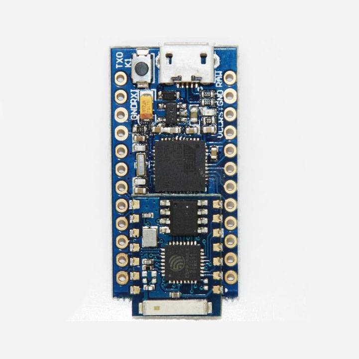
SCF Electronics has adopted this very compact hardware (the Cactus rev.2) with the purpose to develop the TOP on the market of the stand alone Internet-Of-Things (IoT) board.
A single board embeds a 100% Arduino compatible board along with a WiFi module. It is a landmark for the makers who want to develop low power IoT projects quickly and easily. The micro-controller unit is the Atmel ATmega32U4 while the WiFi module is based on the ESP8266. To highlight that the WiFi module firmware has been completely changed with respect the other boards in the market, we chose to name it SCF-TOP03.
POWER PINS
There are a variety of power and power-related nets broken out:
RAW is the unregulated voltage input. If the board is powered via USB, the voltage at this pin will be about 4.8V (USB’s 5V minus a schottky diode drop). On the other hand, if the board is powered externally, through this pin, the applied voltage can be up to 9V.
VCC is the voltage supplied to the on-board ATmega32U4. It’ll be 3.3V. This voltage is regulated by the voltage applied to the RAW pin. If the board is powered through the ‘RAW’ pin (or USB), this pin can be used as an output to supply other devices.
RST can be used to restart the ATmega32U4. This pin is pulled high by a 10 kOhm resistor on the board, and is active-low, so it must be connected to ground to initiate a reset. The ATmega32U4 will remain “off” until the reset line is pulled back to high.
GND, is the common, ground voltage (0V reference) for the system.
I/O PINS
The board’s I/O pins – 18 in all – are multi-talented. Every pin can be used as a digital input or output, for blinking LEDs or reading button presses. These pins are referenced in the Arduino IDE via an integer value between 0 and 21. (The A0-A3 pins can be referenced digitally using either their analog or digital pin number).
Nine pins feature analog to digital converters (ADCs) and can be used as analog inputs. These are useful for reading potentiometers or other analog devices using the analogRead([pin]) function.
There are five pins with pulse width modulation (PWM) functionality, which can be used as analog output using the analogWrite([pin], [value]) function. These pins are indicated on-board with a faint, white circle around them.
There are hardware UART (serial), I2C, and SPI pins available as well. These can be used to interface with digital devices like serial LCDs, XBees, IMUs, and other serial sensors.
The board has five external interrupts, which allow you to instantly trigger a function when a pin goes either high or low (or both). If you attach an interrupt to an interrupt-enabled pin, you’ll need to know the specific interrupt to pin map: pin 3 maps to interrupt 0, pin 2 is interrupt 1, pin 0 is interrupt 2, pin 1 is interrupt 3, and pin 7 is interrupt 4.
DIMENSION
39 x 18 x 4 mm
GETTING STARTED WITH YOUR MODULE µPanel
Visit the offical product page http://www.miupanel.com/getting-started/
PROGRAMING EXAMPLES
Visit the offical product page http://www.miupanel.com/top03-basic-examples/
| SKU | PR0001890 |
|---|---|
| Country of Manufacture | Italy |
| Manufacturer | uPanel |